Beating the Heat for Emerging Electronics
Next-generation radio frequency and digital electronics drive new thermal solutions for avionics systems.


Next-generation radio frequency (RF) and digital electronics will generate more power, cranking up heat. This will increase the demand for improved cooling solutions from forced-air to liquid-cooled to microfluidic technologies.
On the leading edge are programs like Intrachip/Interchip Enhanced Cooling (ICECool), the recently completed effort by the Defense Advanced Research Projects Agency (DARPA) to miniaturize and embed cooling technology at the chip level in both RF and digital components. As former program manager Avram Bar-Cohen put it, “Thermal limits are not divinely imposed like the speed of light or sound.” Solutions can be engineered for tough problems.
“ICECool changes the equation,” added John Ditri, a senior fellow with Lockheed Martin, which worked on the RF side of the program. “By providing better thermal management, temperature no longer becomes a limiting factor, and you can push the chips much harder, thus increasing their performance, until some other mechanism, such as electrical breakdown, starts becoming the limiting factor.” Removing thermal bottlenecks improves performance.
ICECool was the capstone of 15 years of DARPA thermal management programs, said Ken Plaks, program manager with the agency’s microsystems technology office. On the RF side, companies like Raytheon and Lockheed Martin worked on power amplifiers, looking at applications such as radar and electronic warfare (EW) systems. EW systems require a lot of power to blast RF energy at enemy radars over a wide spectrum.
On the RF side of ICECool, DARAP has “demonstrated the ability to get [up to] four times the output power by keeping the electronics cool — or cooler than they would have been — by an order of 20 deg C,” which works out to a fourfold increase in reliability for the class of compound semiconductor material used, Plaks said, although some researchers beat this mark.
RF components can generate tiny hot spots, dissipating more than 60,000 watts per square centimeter. The ICECool metric for RF hot spots was to take out 30,000 watts per square centimeter, and DARPA succeeded in getting it out, he said.
Digital Side: The 2.5-D Challenge
Digital processing is challenging, too, with Moore’s Law slowing down, as it gets harder and harder to do transistor scaling. We’re able to do 14-nanometer transistors today — that’s about 40 atoms across, Plaks said. Seven-nanometer transistors — about 20 atoms across — are coming soon, and 3- and 4-nm transistors are on the drawing board.
“Physics hates you down there,” Plaks said. “You’re trying to manipulate individual atoms on an industrial scale.” That’s one reason designers are looking at 2.5-D and 3-D-stacked configurations, although these technologies compound thermal challenges.
The emergence of 2.5-D and 3-D heterogeneously integrated configurations is driving digital electronics and their cooling needs, agreed Muhannad Bakir, professor of electrical engineering at Georgia Institute of Technology. Under the ICECool program, the school worked on thermal solutions for field programmable gate arrays (FPGAs), reconfigurable logic common to military sensor-processing applications such as radar beam-forming.
In follow-on work with DARPA, the Georgia Tech researchers will be looking at extending their ICECool technology to more complex, 2.5-D, heterogeneously integrated FPGAs. These processors complicate cooling solutions because they involve many dies, generating different levels of power and dissipating different amounts of heat.
2.5-D integration involves bringing bare die, associated with different functions, very close together on a substrate, using a very high-density interconnect. 2.5-D heterogeneous architectures bring into close proximity devices, structures and materials that were not originally intended to be integrated together. Designers also have to keep interconnects very short to minimize computational latencies and energy consumption.
RF Challenges
On the RF side of ICECool, a lot of researchers initially tried to grow diamonds on the back of gallium nitride (GaN) substrates that are used to make monolithic microwave integrated circuits (MMICs). One of the problems, Plaks recalled, was that you have to grow diamond at 800 deg C. When you put the diamond on the back of a GaN wafer, you’re trying to keep the front of it, with the transistors, “cold,” he explained. “We ended up having a hot side and a cold side,” he said, “so the wafers were warping and bending.” It turned out to be very difficult and expensive.
Raytheon, however, found a way to etch channels in the diamond and to attach the diamond to the chip using a more mature process. Because growing diamond directly on GaN devices proved to be ahead of the curve in terms of manufacturability and repeatability, Raytheon switched to a more established GaN-on-silicon carbide (SiC) process, bonding the diamond material to the chip substrate, explained Dave Altman, an engineering fellow with the company. Over the next three years, the company aims to move the ICECool technology from the lab to the point where it’s ready for prime time.
Raytheon applied a technology used in the high-power laser diode industry to attach the diamond to the GaN-on-SiC substrate. That industry also uses microchannel technology to cool gallium arsenide (GaAs) emitters. This bonding approach has not been attempted with GaN RF devices before, Altman said.
The company demonstrated a wideband, continuous-wave amplifier that was smaller in size, with 3.1 times the power output and 4.8 times the power density of the baseline amplifier currently designed into a next-generation EW system. The temperature and therefore the reliability were basically the same as the baseline component.
To achieve these results, Raytheon brought its coolant (glycol mixed with water) within 100 microns of the active high electron mobility transistors (HEMT). The company thinned down the SiC substrate and came up with a way to etch a “manifolded microchannel fluid structure” into the extremely hard diamond heat sink. The miniature piping system is composed of trenches 10 times as deep as they are wide. Having the channels be “as tall and skinny as possible” also allows Raytheon to maximize the surface area that can be cooled.
Now that the ICECool program has concluded, Raytheon is working to find applications where the new technology could shine, such as compact, very high-power RF transmitters, Altman said. ICECool-enabled, high-power EW components could fit into something small or be used in future EW system upgrades.
Lockheed Martin didn’t use diamond. The company made microfluidic manifolds out of palladium, which carried coolant to the underside of the GaN-on-SiC die. The company employed “a kind of wafer-scale process” and “demonstrated 9 dB more power out just by keeping it cool,” Plaks said. Lockheed Martin’s target application was a high-frequency (Ku-Ka band) amplifier used in radar and EW transmitters, Ditri added.
DARPA also funded the company to fabricate an ICECool-based transmit array under the ICECool contract. This project aims to increase ICECool’s technology readiness level by demonstrating integration into a tactical RF transmit array and by documenting its robustness and performance boost, he said.
Lockheed Martin’s cooling technology is “die-independent,” Ditri added. “Our ICECool approach does not require any modification to the die, so it can be used on any off-the-shelf die from any foundry, opening the possibilities of better thermal performance to everyone.” The company uses the latest wafer-level, 3-D additive manufacturing to produce its microfluidic “cooler” technology, he said. “This allows us to produce hundreds of very precise and repeatable coolers in a single wafer run, greatly reducing per-unit costs and ensuring the highest quality components.” Palladium was chosen not for its thermal properties, but because it is very hard and resistant to erosion, corrosion and wear, thus enabling long operational life.
The Lockheed Martin team met or exceeded the program goals, Ditri said. This included removing 1,000 watts per square centimeter from the base of the chips, while simultaneously cooling local chip hot spots dissipating more than 65,000 watts per square centimeter. By comparison, the Intel Core i7 Extreme processor dissipates only about 80 watts per square centimeter over its base, he said.
The company’s ICECool approach reduced the temperature rise in tested amplifiers by more than 100 deg C (or more than three times) compared to the same chips without ICECool, Ditri said. This enabled the components to work more efficiently and to produce more than double the output power of identical amplifiers when conventionally cooled. Reliability testing indicates that running the chips three times cooler will also increase their lifespan by a factor of more than 1,000 times, he said.
One of the key remaining challenges is the integration of the technology into individual platforms. Lockheed Martin believes that ICECool technology could be incorporated into some platforms within a year and that further development of technologies such as improved microfluidic interconnections could expand the scope of possible insertions within a few years. The company is looking into multiple opportunities to incorporate ICECool technology, including Ka band and other frequency band radars and EW systems.
Georgia Tech
Georgia Tech’s FPGA with its original air-cooled system was only able to use about 60% of the chip in running its sample radar-processing application. Otherwise it would get too hot, Plaks said. But thanks to its cooling technology, Georgia Tech was able to achieve 50% more performance on an FPGA card. Using a second microfluidically cooled FPGA card, researchers also have shown that it would be possible to double the processing density to use two cards rather than one in the same volume. “Basically you’re bringing water closer to where the heat is, so you get more effective heat transfer,” Plaks said. Instead of using a cold plate, they “ran water directly into the FPGA.”
Georgia Tech collaborated with FPGA manufacturer Altera (now a part of Intel) to show the benefit of single-phase, microfluidic cooling on a functional CMOS die manufactured in a traditional monolithic architecture, where the transistors are incorporated into a single piece of silicon, Bakir explained.
Georgia Tech’s microfluidic cooling solution, in which deionized water was pumped through tiny channels etched into the back side of the silicon die, reduced the chip’s operating temperature to about 25 deg C, compared with a temperature of about 61 deg C using the device’s original air-cooled technology, said Tom Sarvey, the Georgia Tech graduate student who etched the microchannels and performed the temperature measurements.
Because the microfluidic cooling system is so much more effective than the original forced-air system, all of the capacity of the FPGA could be used without running into performance-degrading thermal limits. Performance increased because more of the chip could be kept on. Also, thanks to the cooling solution, two boards rather than one may be able to operate in the same volume. Equally important, the technology can leverage materials, structures and devices already proven in high-volume semiconductor production, Bakir said.
Georgia Tech was able to demonstrate what Bakir thinks is the first monolithic microfluidic heat sink on a functional 28-nm CMOS die and the first on an FPGA. The liquid came to within “a few hundred microns” of the active transistors. And there is no reason why the distance can’t be smaller, he added.
Water transfers heat at least 10 times better than air, explained Yogendra Joshi, a Georgia Tech professor of mechanical engineering and also the principal investigator in an earlier phase of the ICECool program. This means that you can carry away a larger amount of heat using less power with a denser, high-heat-storage-capacity fluid-like water, compared with air. Deionized water also has high “electrical resistivity,” meaning that the circuits won’t short out if the fluid leaks out of the cooling system. Water’s resistivity, however, can decrease over time, and water freezes at a relatively high temperature, which is why researchers are looking at dielectric coolants, heat transfer oils and refrigerants, Joshi said.
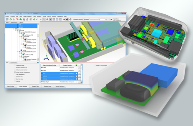
Thermal Analysis Software: Mentor Graphics
Mentor Graphics, a Siemens business, has been a force in thermal analysis since 2008 with tools like FloTHERM and T3Ster. Users of Mentor software include the likes of Rockwell Collins, Curtiss-Wright and Mercury Systems, according to Mentor.
Size, weight and power (SWAP) may be more of a constraint in avionics than in other industries, said John Wilson, electronics products specialist with Mentor’s mechanical analysis division. Designers of an avionics system “have a constrained set of conditions,” such as the amount of air they can get and the not-to-exceed temperature.
Massively parallel graphics processors are among the worst heat offenders, but application–specific ICs generate a lot of heat, too, Wilson said. Microprocessors and FPGAs are also becoming smaller and faster. Mentor Graphics’ web site hosts a case study by Mercury Systems, a designer of sensor-processing subsystems. Mercury describes its use of FloTHERM to analyze an air-cooled XMC product design. It discovered via computational fluid dynamics simulation that it could get a 5 deg C processor thermal reduction that would apply to a range of mezzanine modules. AVS